SAB Assembly Instructions


1.

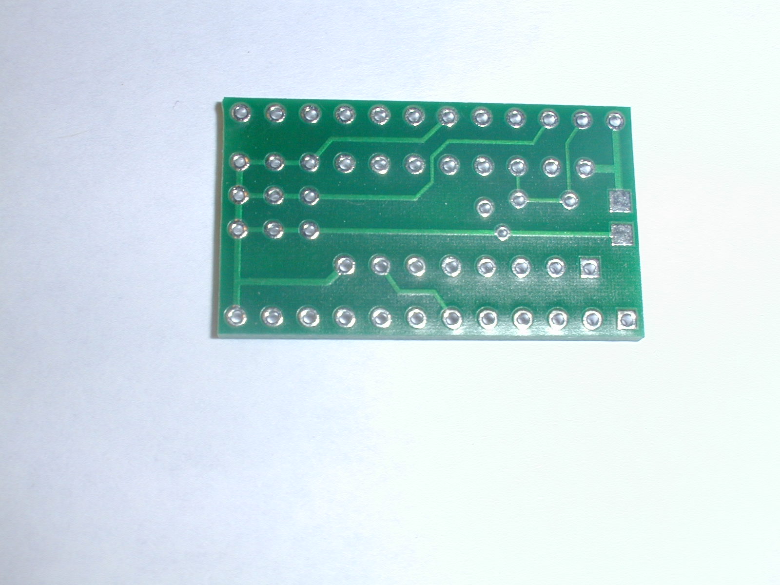
Lay the pc board with the face down on a flat heat resistant surface.

SAB-1.JPG (222995 bytes) 2. Install the 16 pin header as shown.  SAB4.JPG (94293 bytes) 3. While leaving the PC board on the flat surface solder the four corner pins of the header to the PC board.  
  
4. Flip the board over to ensure that the pins are flush with the top of the board. SAB7.JPG (51428 bytes) 4. Solder the remainder of the pins.  Inspect each pin to ensure there are no bridges or cold solder joints. SAB5.JPG (78098 bytes) 4. Flip the board over and the solder the top side of each pin to ensure that you have a good solder joint completely through the board. The top side of the 16 pin header should look like the picture to the right when you are finished soldering.  Inspect each pin to ensure there are no bridges or cold solder joints. (You can clean the flux from this side of the board now).
   
SAB10.JPG (81812 bytes) Inspect the top and bottom solder joints of each pin to ensure there are no bridges or cold solder joints. (You can clean the flux from the board now). 5.

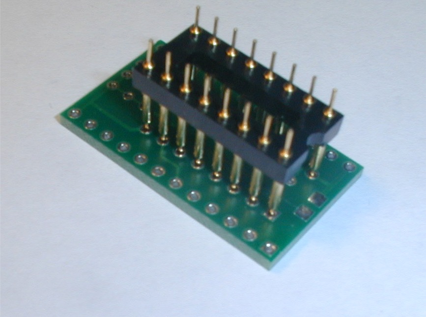
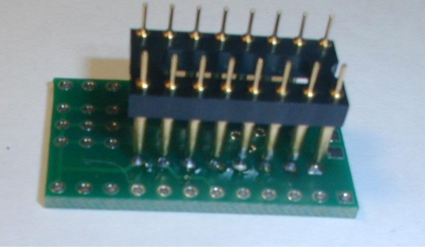
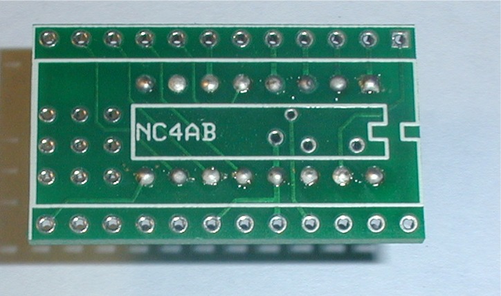
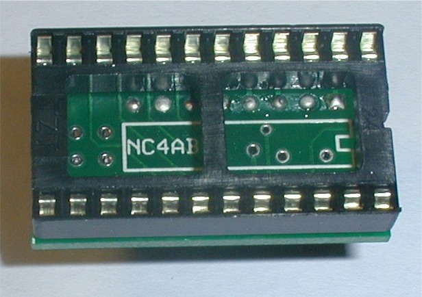
Install the 24 pin IC socket as shown. SAB12.JPG (75687 bytes) 6.

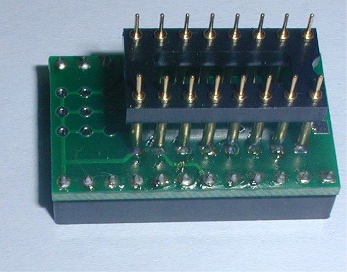
Flip the board over and solder all pins of the socket.  After you have finished soldering,  inspect each pin to ensure there are no bridges or cold solder joints.
   

SAB13.JPG (91947 bytes) 7.  Click here to see how to program & install the SAB in a SYNTOR Radio